NIFF files are binary files therefore close attention must be made to the handling of floating point decimals, etc.
4-2. About File Headers
A NIFF file is a compilation of node lists. Even though some NIFF files do not have all of the NIFF node lists, the header information for the node lists must be stored in all cases. In other words, even if there is no node-related content, be sure to create files as though there were node lists. The data *_list_num_byte = 0 does not exist.
The version value is the area of the file header in which the NIFF version number is stored. Store the version number according to the protocol described below.
The version value is divided into 4 data segments of 8 bits each, as illustrated in Figure 22 below.
Store the Creator Code and Tool Code according to Figure.
Store the NIFF Major Version and NIFF Minor Version according to the version number of the applicable NIFF Specification, as shown in the examples in the table below.
When NIFF Specification Version = 1.2
Major version = 0x01, Minor version = 0x20
When NIFF Specification Version = 0.98
Major version = 0x00, Minor version = 0x98
4-3. About SceneList
Data that is linked to a SceneList includes Obj, Light, Cam, and Env. The handling of Obj nodes, however, differs slightly from that of the other nodes. Even if there are several Obj nodes directly linked to a SceneList, they are enabled only when they have all been converted to N64 data (NIFF to DL). Light, Cam, and Env nodes, however, are enabled when the nodes linked by default using scene_light_link_index(0), scene_camera_link_index(0) and scene_env_link_index(0) are converted to N64 data. Nodes linked otherwise are enabled according to the options in the NIFFtoDL command.
For these reasons, you should normally allot nodes to various index 0 areas. Use index 1 and higher areas when you want to switch these nodes (without using Switch nodes) when previewing data directly on the Nintendo 64 using a tool-independent Plugin or something similar.
scene_cfg stores the flags for setting the video interface (VI) environment in which to preview when previewing data on the Nintendo 64 console.
Of the VI flags that are specified by the various N64 OS osViSetMode() functions, the SCENE_CFG_VIDEO_* flags store settings for NTSC, PAL, and MPAL. However, only NTSC is supported by the initial version converter and previewer. In addition, while the resolution setting, anti-alias setting, etc. of the VI can be set with the osViSetMode() function, the converter and previewer are compatible only with the 320x240 pixel interlaced video mode using anti-aliasing.
SCENE_CFG_GAMMA, SCENE_CFG_DITHER and SCENE_CFG_DIVOT turn ON/OFF the gamma correction, dithering, and divot processing specified with the various N64 OS osViSetSpecialFeatures() functions. It would be ideal to be able to set these in the NIFF file setup window in CG Tools.
Use
to set scene_cfg default values.
Obj nodes differ from other modes in NIFF in that links cannot be extended from multiple Obj to the same Obj node. Similarly, multiple links cannot be extended from a Scene node to the same Obj node. There can always and only be one link to an Obj node. The Obj node itself does not have any concrete 3D data. The configuration of the Obj itself is determined by extending links to nodes with various data, such as Shape, Anim, and Coll. In other words, the Obj itself can be thought of as the label for a character that exists in 3D space. In fact, memory can be more efficiently utilized and labor can be saved in the creation of data by extending links from multiple Obj nodes to the same Shape data.
obj_state data is used when you want to temporarily display a node below an Obj when previewing NIFF data. Set this data in the OBJ_STATE_ACTIVE flag when outputting NIFF data from normal CG Tools.
obj_type is the flag that specifies what type of object an object is. There are 3 types of objects in the current version: NULL object, 3D object, and billboard object.
A NULL object is an object without a shape node. For example, a NULL object is used when you want to specify camera animation or link criteria or matrixes per character unit.
A 3D object is an object with normal 3D shape data. When converted to NIFF data from normal CG Tools, Shape data is linked from this type of object.
A billboard object is an object that is always looking at something (is always facing something). For example, it is more efficient to apply a texture, such as a tree texture, to a single polygon and set it as a billboard object that always faces in the direction of the camera rather than to construct a tree with 3D
polygons.
The data that can be used in the Obj area is limited by the obj_type. Be aware that there is data that cannot be described by an obj_type.
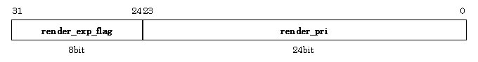
obj_render_pri is the flag that sets the rendering priority order. With the bit configuration shown in Figure 23, the 8 most significant bits are the expansion flag, and the 24 least significant bits are the priority order description field.
Store any of the following flags in the render_exp_flag expansion flag in the 8 most significant bits.
OBJ_RENDER_FLAG_NIFF is a flag for setting the NIFF-dedicated rendering mode and rendering priority order. When this flag has been specified, the rendering mode is defined according to the flag indicated by render_pri. Consequently, the obj_render_type* field is not referenced. Any of the following flags can be specified in render_pri.
In addition, when OBJ_RENDER_FLAG_N64 has been specified by render_exp_flag, the N64 rendering mode specified by obj_render_type* is used as it is as the rendering type, and rendering is performed according to the priority order in the render_pri field.
obj_render_type0 and obj_render_type1 are flags for specifying the rendering mode setup in Nintendo 64. The bit configuration illustrated in Figure below demonstrates the customizability of these flags.
Figure: Data Configuration of obj_render_type0 and obj_render_type1
Since the 10 most significant bits are an unused flag, fill them with 0's (zeros).
The render_mode flag is used to directly specify the Nintendo 64 rendering mode. The table below demonstrates how render_mode is used to set a flag in each individual bit.
Please refer to the Nintendo 64 Online Programming Manual for information on setting these rendering modes on the N64.
As illutrated in Figure below, Obj can modify a linked Obj according to its LOD level. LOD stands for Level of Detail and is a function that switches Obj data to different resolutions according to the distance between the camera and the Obj. When using data in a game, it is important to implement these kinds of performance improvements. Normally, the distance between the camera and the Obj is calculated from the local coordinates of the camera and the Obj. First, obj_lod_num is used to indicate the LOD value of the Obj.
Specify
when an Obj is not to be modified according to the LOD of the Obj.
When
there is only 1 Obj linked to Obj, just as when obj_lod_num = OBJ_NOLOD. But when the distance between the camera and the Obj is greater than obj_lod_dist(0), it is the same as when the Obj does not have a linked object. Consequently, use this when you do not wish to display an object when the camera becomes separated from it by a certain distance.
When obj_lod_num > 1, perform LOD processing for only that number. For example, consider the case when obj_lod_num = 3, as illustrated in Figure below.
Figure: LOD Display When obj_lod_num = 3
When obj_lod_num = 3, the Obj has 3 LOD distance data -- obj_lod_dist(0) - obj_lod_dist(2) -- and 3 Obj data -- obj_lod_link(0) - obj_lod_link(2).
When the distance from the camera to the Obj is greater than obj_lod_dist(2), the Obj is not displayed. Thus, no matter how far the distance from the camera to the Obj, as long as that distance is greater than obj_lod_dist(1), if you wish to always display the Obj of obj_lod_link(2), the Obj of obj_lod_link(2) will continue to be displayed until the far clipping plane is reached, if you set obj_lod_dist(2) = OBJ_LOD_DIST_MAX(0xffffffff).
Since the clipping process and the LOD process are separate, if the clipping plane is closer than obh_lod_dist to Obj, Obj data won't be displayed because it is clipped at the clipping plane.
List the obj_lod_dist(N) in the following order
according to obj_lod_link(N).
Obj that are linked using LOD also are handled as child objects in the same way as Obj that are linked as child objects by obj_child_link. Consequently, the animation properties and Mat properties are all tied together. However, since no more than 1 object can be subject to LOD processing, if you wish to simultaneously LOD-process multiple objects, first link the multiple Obj as child objects of a single NULL Obj, then link that NULL Obj using LOD processing.
4-5. About Shape
The shape_type flag consists of the data that sets anti-aliasing and the Z-Buffer, and that performs face scaling control, etc., in the converter that converts the data to a Nintendo 64 display list. Since this is one of the critical factors that determine the Nintendo 64 geometry mode and rendering mode, make it so that it can be used in the output to NIFF data window and the attribute settings in CG Tools.
Unless set by the user, output the following
as default data.
A Shape node is the only thing that can specify shape data in the NIFF data. Even when a Shape node has several Part nodes, the shape data is defined by the Shape node. Consequently, even if a Shape node is linked to several Part nodes, all triangle data must be linked to the Shape data, regardless of those Part nodes. Therefore, create TriGroup data that is linked from this Shape data in a form that includes the triangle data that specifies the Parts. Part nodes can only ever be used "to partially change a material."
4-6. About Vtx
In NIFF, there is 1 VtxGroup that is linked from a Shape. Therefore, list all of the Vtx data used by the Shape in the VtxGroup affiliated with the Shape. This is the same as essentially creating a Nintendo 64 vertex list.
4-7. About Color
In addition to materials, NIFF can handle triangle colors and vertex colors. These are expressed using TriGroup and VtxGroup that include all of the triangle colors and vertex colors, respectively, used per Shape, regardless of the Parts. However, there are several limitations placed on this data when it is converted to Nintendo 64 data. Refer to section about Mat, for details.
4-8. About Vector
In NIFF, a group of normal vectors for the triangles per Shape uses TriNvGroup, while a group of normal vectors for the vertices per shape uses VtxNvGroup. This data is used when the Mat node settings have been set to use a light (when MAT_SHADE_LIGHT_LOCAL or MAT_SHADE_LIGHT_LOCAL has been specified). Refer to section about Mat, for details.
4-9. About St
In NIFF, a group of St coordinates for the vertices per Shape is used as StGroup.
4-10. About Tri
Tri is a collection of links to the vertex data that comprises one polygon. In addition, TriGroup is a collection of Tri that comprises one polyhedron. The data for a polygon with 4 or more corners must already be divided into triangles when being converted into NIFF. Have the output from CG Tools check these and automatically prompt the user with a warning message asking whether a polygon has been divided into triangles when a polygon with 4 or more corners is used.
4-11. About Part
Some caution is required when handling Parts that are handled by NIFF. Part has no effect on the Shape. It is used only when a material is separated from the Shape. In other words, regarding the triangles that comprise the Shape data, an index number is specified for those not affected by the Mat that is linked to the Shape (or to the Obj on the next higher level), and Part is used when a new Mat is added to those triangles.
Since Parts are handled in NIFF as described above, the tri_group_index in the Part and the tri_group_index in the Shape must be equal. If these settings are different, the Part cannot be expressed accurately.
4-12. About Mat
Mat is an extremely important node in NIFF. When converting data from NIFF to N64, polygon attributes are determined basically by interpreting the Mat nodes. Therefore, please be especially careful when creating NIFF data.
The flags available for specifying material types in Mat are mat_type, mat_shade_type, mat_color_type0, mat_color_type1, mat_alpha_type0, and mat_alpha_type1.
The mat_type flag specifies how the flags set for the material types are applied. The following two specification methods are currently defined.
When MAT_TYPE_NIFF has been specified, mat_color_type* and mat_alpha_type* define the material type according to the respective MAT_TYPE_NIFF specification methods. In this case, the color value and alpha value can use all of the colors which are specified in NIFF.
When MAT_TYPE_N64 has been specified, mat_color_type* and mat_alpha_type* define the material types according to the respective MAT_TYPE_N64 specification method. In this case, all of the color combiner settings on the Nintendo 64 can be performed. However, since color values and alhpa values that do not exist as formats in NIFF cannot be used, it is necessary to allot those values in advance to several user_flags when converting data from NIFF to N64.
Currently, these settings have no effect on mat_shade_type.
The mat_shade_type flag primarily specifies the shading attributes of materials. The following defined flags are currently available.
The MAT_SHADE_LIGHT_* flag is for specifying whether or not to use lights. The MAT_SHADE_LIGHT_OFF flag is specified when there is no lighting, the MAT_SHADE_LIGHT_LOCAL flag is specified when a LOCAL light that is linked to a material is used, and the MAT_SHADE_LIGHT_GLOBAL flag is specified when a light that is linked to the Scene is used.
One of these must be selected. In addition, when MAT_SHADE_LIGHT_LOCAL is specified, it is absolutely necessary to set up a local light, while if MAT_SHADE_LIGHT_GLOBAL is specified, it is absolutely necessary to set up a global light.
MAT_SHADE_FLAT and MAT_SHADE_SMOOTH are flags for toggling between using flat shading or smooth shading.
MAT_SHADE_USE_HILIGHT and MAT_SHADE_USE_REFLECT are flags for specifying highlight and reflection mapping, respectively.
The mat_color_type0 and mat_color_type1 flags relate to color gradations. The mat_color_type1 flag is used only when the 2-cycle mode is set. Since these flags are customized, they are assigned as described below, according to the settings in the mat_type field.
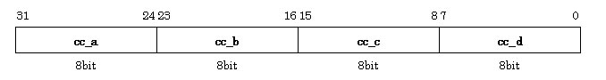
When MAT_TYPE_N64 has been specified, the Nintendo 64 color combiner settings can be directly specified. These are configured as data, as illustrated in Figure below.
Figure: Data When MAT_FLAG_N64 is Specified
The 32 bits are divided in 4 as shown above, with a one color combiner setting flag described in each byte. The cc_* flags are the Nintendo 64 color combiner input sources, as shown below, and can directly be reflected in the g*DPSetCombineMode macro by substiting it. The various input source flags are defined as follows.
Coloring is specified by substituting these for cc_a, cc_b, cc_c, cc_d. These correspond with A, B, C, and D in the internal substitution equation (A-B)*C+D of the Nintendo 64 color combiner. However, these flags are not equivalent to the G_CCMUX_* flags inside the gbi.h file that defines the Nintendo 64 graphics binary interface (GBI). Please keep this in mind when converting. In addition, some of user_flag0-7 are used as input sources for data values that are not supported within the NIFF data. Which of these flags is assigned is specifed in the converter. Please refer to other sections of the NIFF 2.0 Manual for converters released by Nintendo. In addition, use MAT_CC_N64_NONE when color combining is not performed on the 2nd cycle in 2-cycle mode (equivalent to the G_CC_NONE flag in N64).
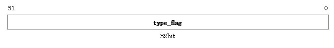
When MAT_TYPE_NIFF has been specified in mat_type, the NIFF-dedicated coloring system is enabled. Since this ultimately will operate on a Nintendo 64, it is reflected in the g*DPSetCombineMode macro, but is different from when MAT_TYPE_N64 described above has been specified in the color data existing in NIFF that is used.
In this case, the data in the mat_color_type* field is used as the NIFF type_flag, as shown in Figure below.
Figure: Data When MAT_FLAG_NIFF is Specified
In this case, the flags listed below that are currently defined by type_flag can be freely combined, bearing in mind the conversion method on the converter side.
However, since you cannot use combinations that are not supported on the converter side, please create data taking the limitations on the converter side into consideration.
mat_alpha_type0 and mat_alpha_type1 are flags for setting alpha gradations. Basically, flags similar to mat_color_type* can be set. However, be aware that there is data that cannot be used in the alpha combiner when the MAT_CC_N64* flag is used.
4-13. About Tex and TexImg
In Specification 1.0, texture data is stored in two lists - TexData and TexImgData. Descriptions regarding format and texture animation during texture conversion are stored in the TexData area, while the image portion in the actual NIFF data is stored in the TexImgData area. This approach makes it possible to have multiple texture data for different animations and different formats that use the same image.
Of course, creating texture data in advance to comply with the Nintendo 64 format is clearly the most efficient method when converting the data into game data. The first priority for the time being, however, is to hold the images in a simple RGBA matrix so that they can be compatible with all formats.
In the future, development is planned that will make it possible to have specific images for each format so that the data can be efficiently used when converted into game data.
4-14. About Anim
The figure below illustrates the current concept of animation in NIFF.
Figure: Concept of Full-Frame Animation in NIFF
Consider a 30-frame full-frame animation like that shown in Figure 28 above. Taking the initial value as "the moment the animation starts" and the final value as "the moment the animation has ended," that piece of animation is stored as data by embedding it in the 29 animation data segments.
In other words, the 0th data is the initial data or base data of that object. Let's take the example of animation data that is Anim(0)-Anim(anim_num-1) in the AnimGroup area. When the data is applied to 30 frames of full-frame animation data,
becomes true, and you have 31 Anim data.
Key frame animation is the same in that, based on the concept of "key frame animation in which all of the frames in full-frame animation are keys", if the anim_num of key frame animation with N keys is considered to be (initial value is 1)+(number of keys)+(final value is 1), then
is true.
Figure: The Convept of Key Frame Animation in NIFF
When looping animation data,
is assumed. Consequently, when converting from NIFF to game data, smooth animation can be reproduced by ignoring either the initial value or the final value.
This concept applies not only to Mtx animation in the Anim area, but also to the various shape animation in the Shape data, and the various texture animation in the Tex data.
In NIFF, notations concerning rotation are expressed using the operation order of rotation angle and rotation matrix for each local axis. The rotation angles for each local axis are described using radians in the clockwise direction relative to the position direction of the corresponding local axis. These are multiplied and used on the application side but, since the rotation operation order differs depending on the tool and since different behavior from the raw data will result if these are mistaken, be sure to set the anim_rot_mtx_order data.
4-15. About Coll
Coll is data pertaining to collisions. In order for an event to occur for certain as the result of a collision in the game application, data is required for determining a collision in connection with the various objects.
Since there are a variety of methods for determining collisions in one game, it is impossible to define them all in NIFF. However, typical data types (with relatively simple processing) are available.
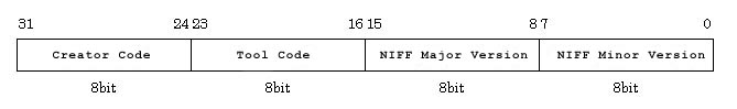 Figure: Data Configuration of NIFF Version Value
4-4. About Obj
SCENE_CFG_VIDEO_NTSC | SCENE_CFG_DITHER | SCENE_CFG_DIVOT
OBJ_RENDER_FLAG_NIFF	0x00
OBJ_RENDER_FLAG_N64	0x01
OBJ_RENDER_NIFF_OPA_SURF	0x00d00000
OBJ_RENDER_NIFF_OPA_INTER	0x00b00000
OBJ_RENDER_NIFF_OPA_DECAL	0x00900000
OBJ_RENDER_NIFF_TEX_EDGE	0x00700000
OBJ_RENDER_NIFF_XLU_SURF	0x00500000
OBJ_RENDER_NIFF_XLU_INTER	0x00300000
OBJ_RENDER_NIFF_XLU_DECAL	0x00100000

bit
NINTENDO64 Rendering Modes
21
AA_EN
20
Z_CMP
19
Z_UPD
18
IM_RD
17, 16
CVG_DIST (0=CLAMP, 1=WRAP, 2=ZAP, 3=SAVE)
15
CLR_ON_CVG
14
CVG_X_ALPHA
13
ALPHA_CVG_SEL
12
FORCE_BL
11, 10
ZMODE (0=OPAQUE, 1=INTER, 2=TRANS, 3=DECAL)
9
ALPHA_COMPARE_EN
8
DITHER_ALPHA_EN
7, 6
BLENDER_MUX_P (0=pix_rgb, 1=mem_rgb, 2=blend_rgb, 3=fog_rgb)
5, 4
BLENDER_MUX_M (0=pix_rgb, 1=mem_rgb, 2=blend_rgb, 3=fog_rgb)
3, 2
BLENDER_MUX_A (0=cc_alpha, 1=fog_alpha, 2=shade_alpha, 3=0)
1, 0
BLENDER_MUX_B (0=(1 - a_mux), 1=mem_alpha, 2=1, 3=0)
obj_lod_num = OBJ_NOLOD(0x00000000)
obj_lod_num = 1

First, if the distance from the camera to the object is less than obj_lod_dist(0), the Obj data linked with obj_lod_link(0) is displayed. Similarly, when the distance from the camera to the Obj is greater than obj_lod_dist(0) and less than obj_lod_dist(1), the Obj data linked with obj_lod_link(1) is displayed.
obj_lod_dist(0) < ... < obj_lod_dist(N-1) < obj_lod_dist(N) < ...
SHAPE_TYPE_AA | SHAPE_TYPE_ZB | SHAPE_TYPE_CULL_BACK
	 MAT_TYPE_NIFF		0x00000000
	 MAT_TYPE_N64		0x01010101
MAT_SHADE_LIGHT_OFF	0x00000000
MAT_SHADE_LIGHT_LOCAL	0x00000001
MAT_SHADE_LIGHT_GLOBAL	0x00000002
MAT_SHADE_FLAT		0x00000000
MAT_SHADE_SMOOTH	0x00000010
MAT_SHADE_USE_HILIGHT	0x00000100
MAT_SHADE_USE_REFLECT	0x00000200
MAT_CC_N64_COMBINED		0x00
MAT_CC_N64_TEX0			0x01
MAT_CC_N64_TEX1			0x02
MAT_CC_N64_PRIMITIVE		0x03
MAT_CC_N64_SHADE		0x04
MAT_CC_N64_ENV			0x05
MAT_CC_N64_KEY_CENTER		0x10
MAT_CC_N64_KEY_SCALE		0x11
MAT_CC_N64_COMBINED_ALPHA	0x06
MAT_CC_N64_TEX0_ALPHA		0x07
MAT_CC_N64_TEX1_ALPHA		0x08
MAT_CC_N64_PRIM_ALPHA		0x09
MAT_CC_N64_SHADE_ALPHA		0x0a
MAT_CC_N64_ENV_ALPHA		0x0b
MAT_CC_N64_LOD			0x0c
MAT_CC_N64_PRIM_LOD		0x0d
MAT_CC_N64_NOISE		0x12
MAT_CC_N64_K4			0x14
MAT_CC_N64_K5			0x15
MAT_CC_N64_1			0x0e
MAT_CC_N64_0			0x0f
MAT_CC_N64_NONE			0xffffffff
	MAT_CC_NIFF_VTX			0x00000001
	MAT_CC_NIFF_TRI			0x00000002
	MAT_CC_NIFF_PRIM		0x00000004
	MAT_CC_NIFF_TEX0		0x00000008
	MAT_CC_NIFF_TEX1		0x00000010
	MAT_CC_NIFF_VTX_ALPHA		0x00010000
	MAT_CC_NIFF_TRI_ALPHA		0x00020000
	MAT_CC_NIFF_PRIM_ALPHA		0x00040000
	MAT_CC_NIFF_TEX0_ALPHA		0x00080000
	MAT_CC_NIFF_TEX1_ALPHA		0x00100000
	MAT_CC_NIFF_NONE		0xffffffff

anim_num = 31
anim_num = N+2

(initial value) = (final value)