It takes the form: Chain Root -> Joint0 -> Joint1 -> Effector
The Joint0, Joint1 conversion matrix is obtained by determining the position of Root and Effector.
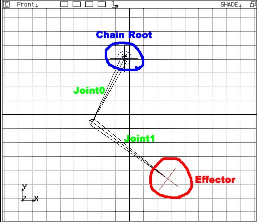
Figure: 2Bone IK

Figure: Joint axis
This plane is fundamentally like in the figure below, where the plane defines the normal line to the Z axis of Joint0 passing through Joint0's point of origin.
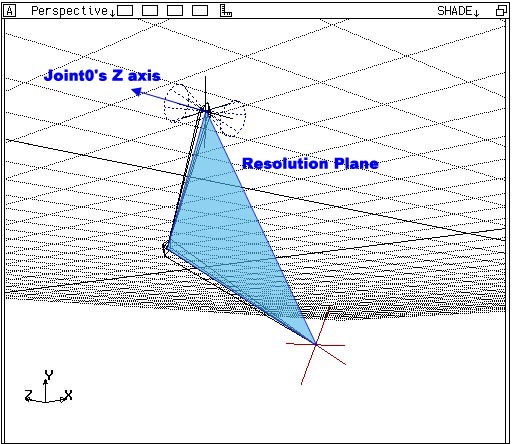
Figure: Resolution Plane
By specifying the axis of the transformed Resolution Plane as shown in the figure below, the original IK movement can be distorted.
In this situation, by applying Preferred Axis Constraint and Up Vector Constraint to Joint0, the object of Constraint can be determined on the original Resolution Plane and then moved on the transformed Resolution Plane where Joint0, Joint1 have been changed.
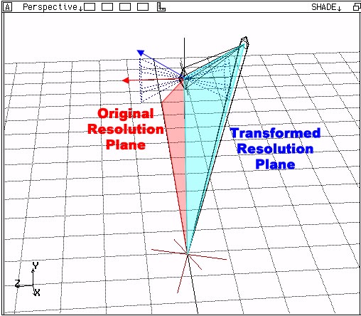
Figure: Transformed Resolution Plane
If the NIFF2_JOINT_UP flag is set in Joint0, then IK will exhibit "bending" movement when the Effector moves in the direction of the Y axis of Joint0, as shown in the figure below.
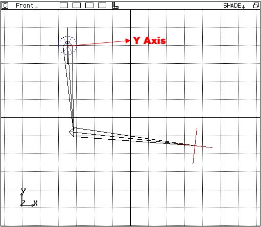
Figure: When NIFF2_JOINT_UP is specified
Conversely, if the NIFF2_JOINT_DOWN flag is set in Joint0, then IK will exhibit "bending" movement when the Effector moves in the direction opposite to the Y axis of Joint0, as shown in the figure below.

Figure: When NIFF2_JOINT_DOWN is specified