The N64 OS was created with a minimum of functions in order to minimize the consumption of resources, and to give greater freedom to the applications.
When using NuSystem for the first time it is important that you understand the differences between an N64 program and a game program. Given that processing is independent in multithreads and messages, you must have advanced programming techniques for such things as thread synchronization and exclusive control of data. NuSystem has taken many of the processes that are common between games and converted them into easy-to-use components.
NuSystem reduces the amount of effort needed in the initial stage of program development, making N64 development easier to understand. In NuSystem, each N64 function is a component which can be controlled using callback and front-end functions - facilitating the progress of N64 programs. The flexible design takes processing speed, memory efficiency, and expandability into consideration. With NuSystem you can create a program without delving into the complicated aspects of N64 development.
To get the most out of N64 development, NuSystem must be customized for each game. Even if you decide not to customize NuSystem it is important that you understand the internal operations of the system. Applying these operations to the program will significantly increase both the reliability and efficiency of your game development.
Moreover, an understanding of the internal workings of NuSystem will give you an understanding of N64 architecture.
INSIDE NuSystem begins by explaining the structure of NuSystem (Chapter 1.) Details about startup and initialization are covered in Chapter 2. The document then provides detailed explanations concerning the internal operations of the scheduler, graphics, audio, controller, SI devices, and PI. There is also a discussion of the methods used for customizing NuSystem.
Please note that significant changes have been made to the audio and controller portions of NuSystem Version 2.0. Therefore we recommend that you read this document even if you are already using an earlier version.
NuSystem can be broadly divided into the following seven components:
Items 2 through 6 are the main components of NuSystem. The Graphics Manager, Audio Manager, and SI Manager are application-independent components, therefore it is possible to create and assemble together application specific components. In this case, not all NuSystem components need to be assembled together (if you do not call the initialization function for a component, it will not be included).
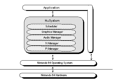
Figure 1.1 shows the relationship between NuSystem and the N64 operating system.

Figure 1.1 Hierarchical Structure of NuSystem and N64 OS
As you can see, NuSystem is situated between the N64 operating system and the application. The application can call the N64 operating system directly or through NuSystem.
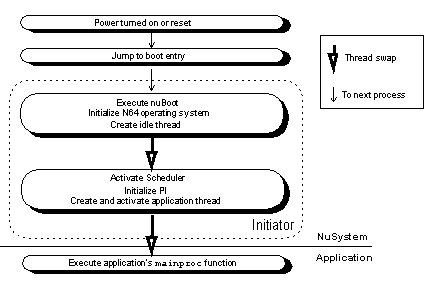
The following figure shows the entire process flow when NuSystem is in use, from the time the N64 power is turned on until the application's entry function (mainproc) is executed:

Figure 1.2 NuSystem Boot Flow
After the power is turned on, the boot entry function (nuBoot) is the first function executed. After the N64 operating system is initialized by the Initiator, the nuBoot function creates and then transfers control to the idle thread. The idle thread starts the Scheduler, initializes the PI, and then creates and executes the thread for the mainproc function, which is the entry point for the application.
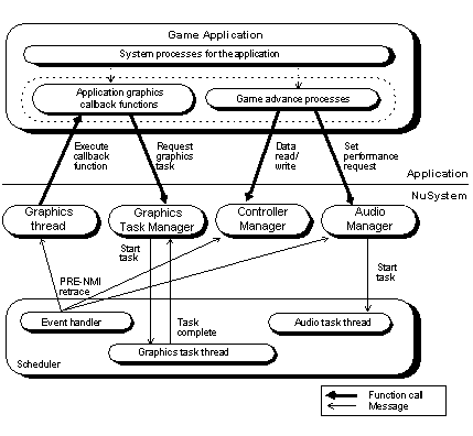
Figure 1.3 shows the basic processes flow between NuSystem and the application.

Figure 1.3 Process Flow Between NuSystem and Application
Each manager is an independent thread waiting for an event message or a message from your application. These event messages are: retrace, PRE-NMI, and end of task. Messages from your application are sent from NuSystem functions.
When a manager receives a message, it checks the type of message and performs the appropriate process. Depending on the situation, it returns a termination message and the data. For example, if the SI Manager receives a retrace message, it uses the serial interface (SI) to read the Controller data. This is done in parallel with application processing.
Note that the application uses NuSystem function calls to gain access to each manager. This is a characteristic of NuSystem. The threads and messages are hidden, and the necessary part of the thread is offered to the application in callback form. If an application prepares a callback function and registers the function pointer in NuSystem, NuSystem(or to be more precise, the manager) executes the corresponding callback function to that event or message.
For example, a device manager like the Controller Manager can use the NuSystem SI Manager to manage devices connected through the SI that require complicated exclusive control thus easing the burden on the application and ensuring exclusive control.
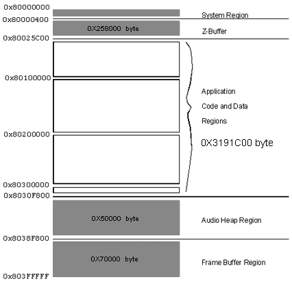
When the nuGfxInit and nuAuInit functions are called at the start of an application, they set the default memory map as shown in Figure 1.4 and proceed to initialize graphics and audio.
The system region is reserved for use by parameter and interrupt vectors.
he Z-Buffer is mapped below the code region. RDRAM has a page register in each 1M memory bank, so memory access is faster when the Z-Buffer is separated from the frame buffer.
By mapping memory in this way, the application allocates a wide contiguous region of memory.

Figure 1.4 Default Memory Map