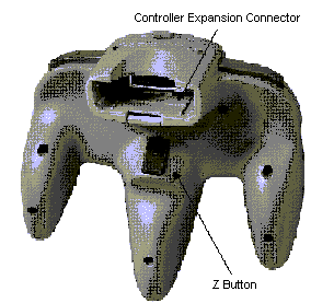
The standard N64 Controller, illustrated below, is a controller standard used by the N64 Control Deck. Please connect the Controller to the Controller Socket to use it. This chapter addresses common questions asked by software developers concerning the standard N64 Controller.
The Standard Controller is illustrated below with names for each button.


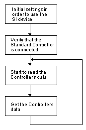
The chart below outlines the flow for a program used to handle the Standard Controller. An explanation of each step follows.

Make the initial settings in order to use the serial interface (SI). Execute the osContInit() function. This need only be done once. With the Controller, there is no need to initialize the SI device itself.
Verify that the Standard Controller is plugged in. This is done by checking the status that is returned after execution of the osContInit() function. To be specific, you need to verify that the value of the "type" member variable of the OSContStatus structure, which is an argument of the osContInit() function, is equal to CONT_TYPE_NORMAL when the value of "type" is masked with CONT_TYPE_MASK. When the Standard Controller is connected, both the CONT_ABSOLUTE bit and the CONT_JOYPORT bit are set in "type." CONT_TYPE_NORMAL incorporates the bits for both CONT_ABSOLUTE and CONT_JOYPORT.
After the first two steps are performed, execute the osContStartReadData() function to begin reading the data from the Controller Pak. Executing this function starts the reading of data from the control stick and the buttons.
As the final step, return the data read from the control stick and the buttons of the Controller to the structure used for storing the data. Execute the osContGetReadData() function. This returns the data read from the Controller's control stick and the buttons to the function's OSContPad structure argument.
By repeating these steps to read and get data, you can build a program which responds to the Controller in real time.
For a concrete example, see the sample program in Section 26.2.4.1 "Obtain Data from the Controller".
Following are descriptions of the the library functions used to handle the Standard Controller in an N64 program.
Function
osContStartReadData, osContGetReadData
Obtain Data from the Controller
Syntax
#include <ultra64.h>
s32 osContStartReadData(OSMesgQueue *mq);
void osContGetReadData(OSContPad *pad);
Description
The osContStartReadData function issues a read data command to obtain the current position of 3D stick and button settings from Controller. The osContGetReadData function returns these data to the location pointed to by the pad argument. You can obtain such information that A button of Controller is pressed down or that how much 3D stick is tilted. These two functions must be paired to use.
The message queue pointed to by the mq argument must be an initialized message queue associated with the OS_EVENT_SI event. Please see the osSetEventMesg() function in the N64 Online Function Reference Manual, for details on how to create this association.
The osContStartReadData function is called only to issue read command, and the message for completed data reading is returned to the message queue mq. Therefore, the osContGetReadData function should be called to obtain data after the osContStartReadData function is called, and osRecvMesg receives a message indicating data reading is completed. The osContStartReadData function takes around 2 milliseconds to complete its data reading and for osRecvMesg to receive a final message. Other processes such as re-drawing the screen can be performed while you are waiting.
You must supply a block of memory large enough for MAXCONTROLLERS structures of type OSContStatus. *8. OSContPad structure is shown below.
*8 If the osContSetCh() function (please see Sectopm 26.1.6.4 "Set the Number of SI Devices to be Accessed") sets the number of direct-type SI devices accessed at a value less than the MAXCONTROLLERS number, then the area secured can be smaller than the MAXCONTROLLERS number, provided more devices are not added later.
typedef struct {
        u16     button;         /* Controller button data */
        s8      stick_x;        /* Control stick's X coordinate position */
        s8      stick_y;        /* Control stick's Y coordinate position */
        u8      errno;          /* Error values returned from the Controller */
} OSContPad;
The Control Stick's coordinate positions stick_x and stick_y are signed characters with the range of -128 ~ 127. However, for the actual program we recommend using values within the ranges shown below:
(See Section 26.2.5 "Programming Cautions" (5) for more information.)
button and the following static variables are ANDed to check which mouse button has been clicked. For instance, button is ANDed with START_BUTTON to check if the bit is ON in order to check if the start button has been clicked.
START_BUTTON is the start button
A_BUTTON is the A Button
B_BUTTON is the B Button
U_CBUTTONS is the C Button Up
D_CBUTTONS is the C Button Down
L_CBUTTONS is the C Button Left
R_CBUTTONS is the C Button Right
U_JPAD is the Control Stick Up
D_JPAD is the Control Stick Down
L_JPAD is the Control Stick Left
R_JPAD is the Control Stick Right
Z_TRIG is the Z Button
L_TRIG is the L Button
R_TRIG is the R Button
If an error occurs when reading data from the Controller, the following error numbers are returned to errno of OSContPad structure. If it is successful, 0 is returned.
CONT_NO_RESPONSE_ERROR
The controller does not respond. The controller is not inserted.
CONT_OVERRUN_ERROR
A communication error has occurred between the N64 Controller Deck and the SI devices. Ignore the data when this error is detected.
Sample
void mainproc(void)
{
        OSMesgQueue     intMesgQueue;
        OSMesg          intMesgBuf[1];
        OSContStatus    sdata[MAXCONTROLLERS];
        OSContPad       rdata[MAXCONTROLLERS];
        u8              pattern;
        int             I;
        int             cont_exist = 0;

        osCreateMesgQueue(&intMesgQueue, intMesgBuf, 1);
        osSetEventMesg(OS_EVENT_SI, &intMesgQueue, NULL);
        osContInit(&intMesgQueue, &pattern, &sdata[0]);

        /* Confirm if controller is inserted */
        for(I = 0; I < MAXCONTROLLERS; I++){
                if(((pattern >> I) & 1) && (sdata[I].errno == 0)){
                        if((sdata[I].type & CONT_TYPE_MASK) == CONT_TYPE_NORMAL){
                                osSyncPrintf("controller is inserted in port %d\n", I);
                                cont_exist = 1;
                        }
                }
        }

        /* if controller is inserted */
        if(cont_exist){
                /* start reading controller data */
                osContStartReadData(&intMesgQueue);


                /* Confirm the end of reading */
                osRecvMesg(&intMesgQueue, NULL, OS_MESG_BLOCK);
                /* get controller data */
                osContGetReadData(&rdata[0]);
        }
}
(1) The Control Stick Reset Function
Description
Do not create a command during game play that involves simultaneously pressing the Left, Right, and Start button.
Reason
Simultaneously pressing these three buttons resets the neutral position of the Standard Controller's Control Stick. Thus, make sure that no essential control actions inside the game reset the Control Stick. Conversely, make sure that resetting the Control Stick creates no unexpected operations in the game.
(2) Simultaneously Pressing Up/Down or Left/Right on the Control Pad
Description
Be sure the game does not hang or other problems arise when either the Up/Down, or Left/Right are pressed simultaneously on the Control Pad.
Reason
Depending upon the situation, the user might press Up/Down or Left/Right at the same time.
Reference
As countermeasures to such an occurrence you can:
* Establish the priority for input from Up/Down and Left/Right
* Ignore this kind of input
(3) Manipulation of Unused Buttons
Description
Be sure the game does not hang or other problems arise when the user presses unused buttons during a game. The same goes for manipulation of other Controllers when a game is only designed to play from Controller 1.
Reason
Players sometimes press unused buttons during game play. Unexpected input might also come from peripheral devices.
Reference
Please be especially careful about buttons that are not used during normal game play but are used when the game is run in debug mode.
(4) Playing with the Control Stick
Description
Set some lower value for play with the Control Stick in order to avoid detecting input when the stick has not been touched.
Reason
The coordinates of the Control Stick when it is not being touched are not necessarily set back to the origin. Moreover, the actual position will vary from device to device, and even within the same device from one time to the next.
(5) Upper Limit Value for the Control Stick
Description
The upper limit value which can be input with the Control Stick varies from Controller to Controller. For important manipulations be careful not to set values which cannot be input.
Reason
Control Stick resolution differs from Controller to Controller. Moreover, as a Controller gets old, the uppermost value that can be input with the Control Stick declines. To handle the variation between Control Sticks, we recommend you set the actual usable range to the values shown below.
Reference
Control Stick resolution is described below in detail.
Explanation of Symbols
XA    : Maximum horizontal center stop width (MAX)
XB    : Minimum horizontal counts left (MIN)
XB'   : Minimum horizontal counts right (MIN)
XC    : Minimum horizontal counts with Control Stick in the up/right direction (MIN)
XC'   : Minimum horizontal counts with Control Stick in the up/left direction (MIN)
XC''  : Minimum horizontal counts with Control Stick in the down/left direction (MIN)
XC''' : Minimum horizontal counts with Control Stick in the down/right direction (MIN)
YA    : Maximum vertical center stop width (MAX)
YB    : Minimum vertical counts up (MIN)
YB'   : Minimum vertical counts down (MIN)
YC    : Minimum vertical counts with Control Stick in the up/right direction (MIN)
YC'   : Minimum vertical counts with Control Stick in the up/left direction (MIN)
YC''  : Minimum vertical counts with Control Stick in the down/left direction (MIN)
YC''' : Minimum vertical counts with Control Stick in the down/right direction (MIN)

Initial Values
| XA : | MAX : 7 Count |
| XBM : minimum guaranteed value of XB, XB' | MIN : 70 Count |
| XCM : minimum guaranteed value of XC, XC', XC'', XC''' | MIN : 54 Count |
| YA : | MAX : 7 Count |
| YBM : minimum guaranteed value of YB, YB' | MIN : 74 Count |
| YCM : minimum guaranteed value of YC, YC', YC'', YC''' | MIN : 56 Count |
A Controller which has been used for approximately 5 million direction changes will present these values.
| XA : | MAX : 7 Count |
| XBM : minimum guaranteed value of XB, XB' | MIN : 68 Count |
| XCM : minimum guaranteed value of XC, XC', XC'', XC''' | MIN : 52 Count |
| YA : | MAX : 7 Count |
| YBM : minimum guaranteed value of YB, YB' | MIN : 70 Count |
| YCM : minimum guaranteed value of YC, YC', YC'', YC''' | MIN : 54 Count |
Given the above values, the program's actual range can be calculated, as follows.
Horizontal direction of X axis (one side) = XBM - XA = 68 - 7 = 61 Count
Vertical direction of Y axis (one side) = YBM - YA = 70 - 7 = 63 Count
Diagonal direction of X axis (one side) (45 degree) = XCM - XA = 52 - 7 = 45 Count
Diagonal direction of Y axis (one side) (45 degree) = YCM - YA = 54 - 7 = 47 Count
If resolution is required, then calibration will need to be performed for every game (and for every Controller). However, correcting the Controller every time can create problems related to the fairness of a game. Additionally, if you do not need to worry about the type of game and the central dead zone width (for example knocking down blocks), then the XBM, XCM, YBM, YCM values can act as the actual range in the program.
In short, you'll need to adjust the central dead zone width on the application side in accordance with the nature of the game.
(6) Control Stick Input Values
Description
Make sure that nothing unusual happens no matter what value in the range from -128 to 127 is input, either Up/Down or Left/Right with the Control Stick.
Reason
If the neutral position of the Control Stick is off center, then these values could be input as the maximum (minimum) values.