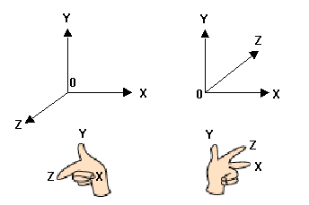
1-3-1 Right/Left Hand Coordinate System
Next, the coordinate system for 3D graphics will be described. A three-dimensional coordinate system can be right-handed or left-handed. The Z-axis direction compared to the X-axis and Y-axis directions, is different. In the right-handed system, the Z axis points out toward the viewer. In the left-handed coordinate system, the Z axis points in away from the viewer. N64 uses the right-handed coordinate system as do most others.

Figure 1-3-1 Right/Left Hand Coordinate System
1-3-2 Model Coordinate System
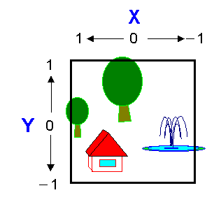
The model coordinate system is the base system used when creating model data for a specific design of an object. Generally, when modeling several objects, you define the coordinate origin, axes, scale, and so on individually so that it is easy to model each object. For example, when modeling a robot's arm consisting of a forearm and an upper arm, you use an individual coordinate system for each of them. Depending on the modeler, the range used as a model coordinate, may be normalized to -1.0< x < 1.0,
 ,
,  . In this case, you have to create the model data within this limitation.
You can use the model coordinate system to define each modeling object independently. For example, when you model an airplane like the one shown above, you might define a length of 1 meter as 0.1 and do modeling in a space where one edge is 20 meters (because the range of each axis is from -1.0 to 1.0). When you model a human head, you could define 1 centimeter as 0.05, and then do the modeling in a space where one edge is 40 centimeters. The coordinates defined in the model coordinate system are expressed as
 . Note that there is no uniform model coordinate system that all 3D modelers of each company use. Each 3D modeler is free to set up their own model coordinate system.
Figure 1-3-2 Model Coordinate System
1-3-3 World Coordinate System
The world coordinate system is like the coordinate system of a photo studio where all the objects are placed together to prepare for a photograph to be taken of the model. In the world coordinate system each three-dimensional object is in a defined location.
The world coordinate system needs a very wide range depending on the world you want to render. For example, in the case of a racing game, you might define 1 meter as 1.0 and render up to 1 kilometer (1,000 meters). In the case of a fighting game, you might define one edge of the world coordinate system to be only 10 meters.
Calculations are necessary when you place each object using a model coordinate system into the world coordinate system. For example, say you define 1 meter as 1.0 for your world coordinate system. When you place the previously illustrated airplane (which was defined with 1 meter as 0.1) into your world coordinate system, you need to reduce the size of the model data to 1/10th its previous size. When you place the human head which was defined with 1 centimeter as 0.05, into the same world coordinate system, you must reduce its size to 1/500th of its previous size. The world coordinate system's coordinates are expressed as
 .
. 
Figure 1-3-3 World Coordinate System
1-3-4 View Coordinate System
The view coordinate system puts the view (camera) at the point of origin and places the direction of the view along the Z-axis. Sometimes it is called the view point coordinate system. Because the drawing processor (the RCP) is like a camera, this coordinate system is what the RCP hardware uses to view the virtual 3D world set up in the computer. The range actually seen is the part that falls inside the rectangular pyramid which is called the "view volume." This becomes the visual field, and a vertex of the rectangular pyramid is like the focus of a camera. The distance between the screen and focus is equal to the focal distance.
When the distance between the focus and screen is long, the angle of the visual field is narrow, and the image seems to be taken with a telephoto lens. When the distance is short, the angle of the visual field is wide and the image seems to be taken with a wide-angle lens.
 .
.
 .
.
 .
. 
