Obviously when you multiply a matrix where
1-6 Geometric Transformations and Matrix
In "1-3 Coordinate System", you learned that you need to convert from one coordinate system to another in order to ultimately display a picture on the TV screen. This section shows you how to actually do the coordinate system transformations by using matrix calculations. Usually,


| Examples of N64 functions (enlargements or reductions) guScale guScaleF |
Obviously when you multiply a matrix where ![]() by any vector, the vector does not change at all. This type of matrix is called an identity matrix.
by any vector, the vector does not change at all. This type of matrix is called an identity matrix.
| An example of N64 function(identity matrix) guMtxIdent |
#Translation matrix to specify movement
The three-dimensional translation matrix looks like this:

The translation matrix is used to translate; it translates the coordinates of an object to move it to a new location. When you multiply this matrix by a vector and expand it, you get the following result:


Figure 1-6-3 Translation matrix
| N64 functions to translate an object's vertex to a new location guTranslate guTranslateF |
#Rotation matrix to specify rotation around an axis of origin
Three-dimensional rotational conversion is more difficult than two-dimensional because there are an infinite number of possibilities for the axis of origin.
However, in most cases, you will specify the rotation of each coordinate axis by using the synthesis method instead of using arbitrary axis rotation (See section 1-6-4, Coordinate System Transformation).
N64 adapts the types of rotation direction described below.

Figure 1-6-4 Rotation directions
*X-axis rotation
x-axis rotation is specified by this matrix:

When you expand the multiplication of a vector with this matrix, each coordinate component becomes:
![]()
As you can see, the ![]() component has not changed.
component has not changed.
*Y-axis rotation
y-axis rotation is specified by this matrix:

When you expand the multiplication of a vector with this matrix, each coordinate component becomes:
![]()
As you can see, the ![]() component has not changed.
component has not changed.
*Z-axis rotation
z-axis rotation is specified by this matrix:

When you expand the multiplication of a vector with this matrix, each coordinate component becomes:
![]()
As you can see, the ![]() component has not changed.
component has not changed.
| Examples of N64 functions (rotation) guRotate guRotateF guRotateRPY guRotateRPYF |
(Remembering the rotational direction of each-axis rotation)
As explained previously, N64 uses the right-handed coordinate system (see section 1-3, Coordinate System).
The general method of deciding rotational direction in the right-hand coordinate system can be expressed as follows:
1. Make the right screw advance to the position direction of the axis.
2. At that time, determine the direction that the right screw rotates as the positional direction.
Following this rule, the positive direction of each coordinate axis rotation looks like this:

Figure 1-6-5 Rotational Direction of Each Axis Rotation
1-6-3 Projection Transformation
Projection conversion calculations determine the level of perspective that will be provided when you display the object seen from the camera on the screen. There are two methods of projection: One is Orthographic Projection. Another is Perspective Projection.
#Orthographic Projection
An orthographic projection shows the view volume (the portion of a 3D space that a camera can capture in a picture) as a rectangular parallel pipe without any perspective at all. The world appears flat but accurate measurements are possible given that you know how close or how far away the objects are in the 3D virtual world. Here is an example:
 |
Figure 1-6-6 Orthographic Projection
"Near" is a value to display from where on the view front (the position where the camera is set) to start to draw, and "Far" is a setting value for until where on the view front to draw.
Given the following settings:
t=top (top of the screen)
b=bottom (bottom of the screen)
r=right (right side of the screen)
l=left (left side of the screen)
n=near clip (position of the near clipping plane)
f=far clip (position of the far clipping plane)
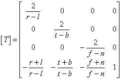
the conversion matrix of an orthographic projection looks like this:

Although this matrix seems to be rather complicated, N64 functions calculate it for you. All you need to do is pass the original settings listed above, so an in depth understanding of the matrix is not necessary.
| Examples of N64 functions (The calculation of the orthographic projection matrix) guOrtho guOrthoF |
#Perspective Projection
A perspective projection shows the view volume (the portion of a 3D space that a camera can capture in a picture) as a quadrilateral pyramid to give the view volume perspective. Here is an example:
 |
Figure 1-6-7 Perspective Projection (frustum)
Given the following settings:
t=top (top of the screen)
b=bottom (bottom of the screen)
r=right (right side of the screen)
l=left (left side of the screen)
n=near clip(position of the near clipping plane)
f=far clip (position of the far clipping plane)
the conversion matrix of a perspective projection looks like this:

| Examples of N64 functions (The calculation of the perspective projection matrix) guFrustum guFrustumF |
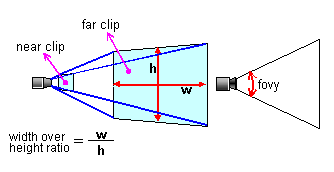
In this matrix the ratio of length to width is 1:1, sometimes making it a little hard to use for actual display on a screen. Therefore, you may need to add a different length to width ratio when preparing your projection matrix as shown here:
 |
Figure 1-6-8 Perspective Projection 2 (perspective)
Given the following settings:
a=aspect ratio(ratio of length to breadth)
Theta=fovy/2 (fovy)
n=near clip(position of the nearest clipping plane)
f=far clip (position of the furthest clipping plane)
The conversion matrix of a perspective projection that includes a length to breadth ratio looks like this:

Now, you can display the object placed in the three-dimensional space.
| Examples of N64 functions (Perspective Projection) guPerspective guPerspectiveF gSPPerspNormalize |
For example, for parallel movement, the conversion expression in OpenGL is:

It would look like this for N64:

The conversion matrix is transverse for OpenGL and N64.
1-6-4 Coordinate System Transformation
Coordinate transformation was explained earlier by being categorized into transformations (scaling, translation, and rotation). This section explains how to transform the coordinates of one coordinate system into those of another, one after another, while moving through the coordinate transformation flow. The conversion matrix to convert from coordinate system 1 to coordinate system 2 will be depicted as ![]() , from coordinate system 2 to coordinate system 3 as
, from coordinate system 2 to coordinate system 3 as ![]() , and from coordinate system 3 to that of 4 as
, and from coordinate system 3 to that of 4 as ![]() . Coordinates in each system for a point P will be depicted as
. Coordinates in each system for a point P will be depicted as ![]() ,
, ![]() ,
, ![]() ,
, ![]() . Therefore, when you convert from one coordinate system to another in order, the following formulas apply:
. Therefore, when you convert from one coordinate system to another in order, the following formulas apply:
![]() (equation 1: conversion equation from coordinate system 1 to coordinate system 2)
(equation 1: conversion equation from coordinate system 1 to coordinate system 2)
![]() (equation 2: conversion equation from coordinate system 2 to coordinate system 3)
(equation 2: conversion equation from coordinate system 2 to coordinate system 3)
![]() (equation 3: conversion equation from coordinate system 3 to coordinate system 4)
(equation 3: conversion equation from coordinate system 3 to coordinate system 4)
Next, if you substitute equation 1 for equation 2 and substitute the result for equation 3, you can go from the equation for coordinate transformation from coordinate system 1 to that of 4 in a single equation:
![]() (equation 4: conversion equation from coordinate system 1 to that of 4 in a single process)
(equation 4: conversion equation from coordinate system 1 to that of 4 in a single process)
A process that provides several conversions in a row like this is called a conversion synthesis. As you can see from the equations given above, a conversion synthesis involves the multiplication of conversion matrices.
Next, we will apply this to a game situation. Obviously, a single model has several vertices, and you need to provide an identical coordinate transformation for each vertex. However, to provide the same matrix multiplication repeatedly is inefficient. Therefore, do the matrix multiplication first. Then, use the matrix to convert from the first coordinate system to the last coordinate system in one process for better calculation efficiency.
For example, if:
![]()
then ![]() becomes the conversion matrix from coordinate system 1 to that of 4. Thus, you can specify equation 4 using the following simple form:
becomes the conversion matrix from coordinate system 1 to that of 4. Thus, you can specify equation 4 using the following simple form:
![]() (conversion equation from coordinate system 1 to coordinate system 4)
(conversion equation from coordinate system 1 to coordinate system 4)
Therefore, when you actually draw an image, you can provide a single coordinate transformation calculation to convert directly from the model coordinate system to the normal screen coordinate system at once. Accordingly, it is not necessary to separately perform the world and view coordinate system conversions.
Remember, however, that matrix multiplication is not commutative; that is, you can't switch the order and get the same result. Therefore, when you provide the conversion by using matrices, you need to be careful of the order in which you multiply them. If you multiply in the wrong order, a completely different result will be produced, as shown in the following illustration. Similarly, when you provide several rotational conversions, the result is very different depending on the order of rotating axes. In other words, XYZ will give a result very different from YXZ. This is very important, and you must be careful.
 |
Figure 1-6-9 Differences based on the order of matrix multiplication
Note that the 3D modelers sold by various third-party companies are not standardized in terms of the directions of axes, directions, names of axes, rotational orders, or rotational directions that are used. Therefore, with the rotation of a polygon model, you need to verify the rotational procedures used by modelers before utilizing their output data.