5-4 Tutorial
This section describes the program compilation/link, creating the ROM image file and debugging methods by using an actual sample. Before you use the sample, we will describe the procedure for creating the ROM image file. Once you understand this you can proceed.
5-4-1 Procedure for Creating the ROM Image File
The ROM image file is created by designating the object file and the picture/sound data to the ROM image creation tool after you have created the relocationable object file with the compiler/linker.(Relocationable object file: Object files where the function and argument addresses have not been determined.) The ROM image creation tool outputs the ROM image file and the debugger symbol file. The default name of the ROM image file is "rom" if not specified otherwise. Specify the symbol file name between "beginwave" and "endwave" of the spec file designated to the ROM image creation tool.
5-4-2 Compilation/link/creation of the ROM image using an actual sample
Now let us do the compilation/link/creation of the ROM image with an actual sample. Here, we will use the sample called "simple." "simple" has been installed in the directory, "/user/src/PR/simple." Copy it to the appropriate directory from the console.
For example, you can create the directory, "simple", copied into the current directory by executing:
% cp -r /usr/src/PR/demos/simple.
1. Makefile
The compilation/link/ROM image creation in "simple" are provided by using the program, "make." "make" provides the process based on the contents defined in the text file, "Makefile" (See the outline manual of "make" for details).
Now we will describe the contents defined in "Makefile." Open the text file, "Makefile" in the directory, "simple", with your editor (the actual "Makefile" does not describe the following #comments).
[Makefile]
#!smake
include $(ROOT)/usr/include/make/PRdefs #
Files reserved in the system [defining the
#
compiler name and
#
dependency, etc.]
# to make the tags file do "make simpletags"
# to make just the simple_d directory do "make
SUBDIRS=simple_d"
SUBDIRS=simple_d simple simple_rom #
Specify the subdirectory
# In "simple," you create the following three types of ROM image files
# and symbol files:
# 1. For debugging simple_d
# 2. For ordinary use simple
# 3. For master submitting simple_rom
COMMONPREF = simple #unused
APP = simple #Specifies the symbol file name
TARGETS = rom #Specifies the ROM image file name
HFILES = \ #Specifies the header file name for "simple"
:
CODEFILES = \ # Specifies the .c (the program code) file name
:
CODEOBJECTS = $(CODEFILES:.c=.o)
#Specifies (the program code) file name
#(The name is replaced from .c to .o, which is
#the file name specified in CODEFIELES)
#Example: test.c -> test.o
CODESEGMENT = codesegment.o #Specifies the relocationable
#object file name created as a
#result of linking the program code
# Data files that have their own segments:
DATAFILES = \ #Specifies the .c (data) file name
:
DATAOBJECTS = $(DATAFILES:.c=.o)
#Specifies the .o(data code) file
#name (The name as CODDOBJECTS above)
OBJECTS = $(CODESEGMENT)$(DATAOBJECTS)
#Specifies all relocationable object file names
#specifies to the ROM image creation tool
LCINCS = -I.. -I$(ROOT)/usr/include/PR
#Specifies the pass of the include file specifying to the compiler (for local use)
LCOPTS = $(DFLAG) -fullwarn -non_shared -G0 -Xcpluscomm
#
Specifies the option of specify to the compiler (for local use)
LCDEFS =
#
Specifies the symbol definition to specify to the
# compiler (for local use). Unused in "simple"
LDIRT = load.map
# Specifies the map file name
LDFLAGS = $(MKDEPOPT) -nostdlib
-L$(ROOT)/usr/lib
-L$(ROOT)/usr/lib/PR
-l$(ULTRALIB)
#
Specifies the option to specify to the linker
# MKDEPOPT is a reserved name and the file defined the dependent
# relation of each object file.
# "-nostdlib" is a specification which is not use the standard library.
# "-L$(ROOT)/usr/lib-L$(ROOT)/usr/lib/PR
-l$(ULTRALIB)" is the
# option to link the N64 OS library.
.PATH: .. # The path specification of "simple"
# "simple" is to execute "make" in
#
each subdirectory
include locdefs
#
Accept the setting of each
#
subdirectory. The error does not return even if it fails.
#include $(COMMONRULES)
#
Note that "#" is a comment-out.
default: #
Specifies to provide the following
#
process with default in this
for i in $(SUBDIRS) ; do \ #
"Makefile." Specifies to move to
echo ==== $$i === ; \ #
each subdirectory and execute "make"
cd $$i ; \
$(MAKE) -f ../Makefile loc_$$i ;\
cd .. ; \
done
$(COMMONTARGS) : #
Specifies to provide the process when it specifies
#
the reserved command in the system to "make"
#
Example)make clean
for i in $(SUBDIRS) ; do \ #default:
the same
echo ==== clobber $$i === ; \
cd $$i ; \
$(MAKE) -f ../Makefile loc_$@ ; \
cd .. ; \
done
include $(COMMONRULES) #
Accept the reserved file in the
#
System
install: default #
Specifies to install "simple"
#
The files below are installed.
#
Execute "default" before executing
#
this. If it has not been executed,
#
first execute "default."
$(INSTALL) -m 444 -F
/usr/src/PR/demos/simple \
$(HFILES) $(CODEFILES) \
$(DATAFILES) Makefile spec
\
simple/log.fmt
simple_d/locdefs \
simple/locdefs
simple_rom/locdefs
$(CODESEGMENT): $(CODEOBJECTS)
# Specifies the dependent relation between "code segment.o" and the .o file.
# If the .o file is updated, provide the following process.
$(LD) -m -o $(CODESEGMENT) -r
$(CODEOBJECTS)\
$(LDFLAGS) > load.map
#
Specifies to create the relocationable object file with using the linker
# "-m" specifies to output the map file.
# "-o" $(CODESEGMENT) is an option to specify the output file name.
# "-r" is the option to create the relocationable object file name.
# "$(CODEOBJECTS)" specifies the linking object file name.
# "$(LDFLAGS)" specifies to pass other options to the linker.
rom: ../spec$(OBJECTS)
# Specifies the ROM image file, all ".o" files and the dependent relation of spec file.
# Provide the following process when the .o file and the spec file are updated
$(MAKEROM) $(MAKEROMDEFS) ../spec
# Specifies to create the ROM image file with using the ROM image
# "$(MAKEROSDEFS)"
is the standard option specified to the image creation too.
# "spec" is the text file to specify the ROM image to the ROM image creation, too.
#
We will describe this later.
|
The contents mentioned above are just one example. The compiler/linker/ROM image creation tool has a lot of other convenient functions. Apply them based on the program usage.
2. Specifying the ROM Image
Next, we will describe the contents defined in the script file to specify the ROM image. Open the text file, "spec," in the directory, "simple", with your editor (In the actual "spec," the /*Comments*/ below are not described).
Read the "makerom" online manual
[spec]
/* The ROM image manages in units of segments.*/
/*
Define the segments having the program code attributes.*/
beginseg /*
Initiate to define the segments*/
name "code" /*
Specify the segment names*/
flags BOOT OBJECT
/* Designate the boot attribute and the object attribute*/
entry boot /*
Specify the boot function */
stack bootStack + STACKSIZEBYTES
/*
Specify the stack used by the boot function*/
include "codesegment.o"
/*
Specify the object file mapping within the segment
*/
include "$(ROOT)/usr/lib/PR/rspboot.o"
/*
Specify the boot microcode*/
include "$(ROOT)/usr/lib/PR/gspFast3D.o"
/*
Specify the graphic microcode */
include
"$(ROOT)/usr/lib/PR/gspFast3D.dram.o"
/*
Specify the graphic microcode */
include "$(ROOT)/usr/lib/PR/aspMain.o"
/*
Specify the sound microcode */
endseg /*
End the segment definition */
/* The following is the description only about the parts which */
/*don't overlap with the "code" segments
*/
beginseg
name "gfxdlists"
flags OBJECT /*
Designate the object attribute */
after code /* Specify mapping right after the "code" segment.
*/
include "gfxdlists.o"
endseg
beginseg
name "zbuffer"
flags OBJECT /*
Designate the object attribute */
address 0x801da800 /* Specify mapping on the 0x801da800 address */
include "gfxzbuffer.o"
endseg
beginseg
name "cfb"
flags OBJECT /*
Designate the object attribute */
address 0x80200000 /* Specify mapping on the 0x80200000 address
*/
include "gfxcfb.o"
endseg
beginseg
name "static"
flags OBJECT /*
Designate the object attribute */
number STATIC_SEGMENT /*
Specify the static segment number */
include "gfxinit.o"
include "gfxstatic.o"
endseg
beginseg
name "dynamic"
flags OBJECT /*
Designate the data attribute */
number DYNAMIC_SEGMENT /*
Specify the dynamic segment number */
include "gfxdynamic.o"
endseg
beginseg
name "bank"
flags RAW /*
Designate the data attribute */
include
"$(ROOT)/usr/lib/PR/soundbanks/GenMidiBank.ctl"
/*
Specify the sound bank data
*/
endseg
beginseg
name "table"
flags RAW /*
Designate the data attribute */
include
"$(ROOT)/usr/lib/PR/soundbanks/GenMidiBank.tbl"
/*
Specify the sound table data. */
endseg
beginseg
name "seq"
flags RAW /* Designate the data attribute*/
include
"$(ROOT)/usr/lib/PR/sequences/BassDrive.seq"
/*
Specify the sound sequence data */
endseg
beginwave /* Initiate to define waves*/
name "simple" /*
Specify the symbol file name (ignore ".out") */
include "code" /*
The following are the specification of mapping segments.*/
include "gfxdlists"
include "static"
include "dynamic"
include "cfb"
include "zbuffer"
include "table"
include "bank"
include "seq"
endwave /*
End the wave definition */
|
The above is the required procedure to provide the compilation/link/ROM image creation to the sample with "make."
3. Executing "make"
Now, let us actually execute "make". Execute "make" using the directory, "simple".
% make
With the completion of "make," the ROM image file, "rom", and the symbol file, "simple", are created in three subdirectories. Verify this with the "ls" command, etc.
5-4-3 Executing the Sample
Execute the sample using the ROM image and symbol files which were created in "5-4-2: The Compilation/Link/ROM Image Creation of the Sample." (You use "simple" again here.) Provide the execution of the sample using the command, "gload". Continue using the following procedure:
- Moving the Directory
Move to the subdirectory "simple_d" of "simple."
% cd simple_d
- Executing "gload"
Input "gload" in the moved directory. (If there is no specification of the ROM image file name, "gload" recognizes the file "rom" as the ROM image file.)

Figure 5-4-1 Executing "gload"
- The end of the execution
End with "^c"(Ctrl+C).
5-4-4 Debugging the Sample
This section describes some debugging examples using the sample. Because you use "simple" here again, move to the subdirectory "simple_d" of "simple" in the same way as in, "5-4-3 : Executing the Sample."
1. Activation "gvd"
You need some procedures for using the debugger (the rest is "gvd").
Input commands in the following order on the console:
%dbgif & : Specify the connection of the N64 emulator board
%gload -a "-d" & : Specify the software down_load
%gvd simple & : Specify "simple" to "gvd"
Note: To operate each command on a background, specify "&" at the end. To end this command, verify the process ID of each command with the "ps" command, and specify the process ID to the "kill" command. The "-a" option of "gload" specifies the passing of arguments to the program. In "simple," if the argument "-d" is specified, it provides the process corresponding to "gvd" (see "simple"-"misc.c").
2. Connecting to Targets
The debugging by "gvd" is provided in units of threads. This manual debugs the thread called "simple" - "game Thread". To provide a choice of threads, select "Admin" - "Switch Thread" from the "gvd" main menu with the left mouse button. After you select, the window to input the thread ID is displayed. Input the thread ID here ("game Thread" is 6).
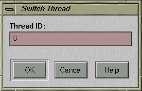
Figure 5-4-2 Selecting the thread
3. The Setting & Cancellation of the Breakpoint
This section describes the setting method of the breakpoint. Set the breakpoint in "simple" - "gfx.c" - "createGFxTask()". Click "Source" - "Open" from the "gvd" main menu with the left mouse button.
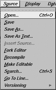
Figure 5-4-3 Open the source
After you select, the file list box is displayed. Select "gfx.c" and click the "OK" icon with the left mouse button.
Note: The directory (Selection) right after the "gvd" activation is the subdirectory of "simple". Select the directory after correcting it to the directory having "simple".
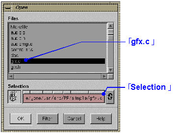
Figure 5-4-4 Select the file
After you have selected the file, the content of "gfx.c" is displayed in the "gvd" source window. Use the scroll bar and scroll the source until "createGfxTask()". The 127th line of "gfx.c" has a place to bring up the "assert()" function. Move the mouse cursor to the left margin of the source window and click. Then, the line color bringing up the "assert()" function of the source window is highlighted and a downward arrow is displayed in the left margin. Now you have finished setting the breakpoint.

Figure 5-4-5 Select the line calling the "assert( )" function
Next, click the "continue" button with the left mouse button and execute the program.
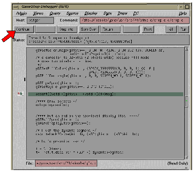
Figure 5-4-6 Setting/cancellation of the breakpoint
After executing, the color of the line set as the breakpoint is highlighted, and a sideways arrow is displayed in the left margin and the program breaks. To free the breakpoint, click the left margin with the left mouse button in the same way as with setting. After clicking, the downward arrow in the left margin disappears. Now you have freed the breakpoint.
4. Step Execution & Trace Execution
This section describes step execution and trace execution of the program. First, complete the steps in "3. The Setting & Cancellation of the Breakpoint". After the break, provide the step execution. For the step execution, click the "Step Over" button with the left mouse button, or input "n" on the command input window. After clicking, the line which was highlighted on the source window moves along through the program process, and the sideways arrow in the left margin moves with it. This shows that the step execution is being carried out.
Figure 5-4-7 Step Execution
For the trace execution, click the "Step Into" button with the left mouse button, or input "s" in the command input window. The difference between the trace execution and the step execution is that if a function is brought up, the trace execution goes into the function, but the step execution just provides the function call and does not go into the function.
5. The Dump & Editing
This section describes the dump and editing functions. First, complete the steps described in "3. The Setting & Cancellation of the Breakpoint". After the break, carry out the dump.
In "createGfxTask()", the data setting is provided to the argument "glistp". Dump this content. Select "Views" - "Memory View" from the "gvd" main menu with the left mouse button. After the selection, the "Memory View" window is displayed. Input "glistp" to "Address" and press the "Enter" key. After the input, the dump data is displayed in the window.
 |
Figure 5-4-8 Display the dump data
This section describes the dump methods in units of byte. However, in "Memory View" you can change the notation of the numeric values(decimal notation and hexadecimal notation, etc.), depending on the menu "Mode", or the dump unit depending on the menu "Size".
Next, the editing will be done.
The editing also uses "Memory View" in the same way as the dump.
First, provide the same content as described for the dump.
Next, input "0xff" in "value" and click on the "modify" button with the left mouse button.
 |
Figure 5-4-9 The editing
After the click, try to dump "glistp" again and you will notice that the first byte has been changed to "0xff"
6. Refer to Arguments of C
This section describes about the source code debugging function referring to arguments of C. First, provide the content described in "3. Setting & Cancellation of the Breakpoint". After the break, provide the reference of arguments. Next, provide the reference using the "p" command from the command input window. In "createGfxTask()", the local argument "dynamicp" is passed to the "doLogo()" function. Input the following command in the command input window:
gvd> p *dynamicp
Because "dynamicp" is a pointer type, "*" specified at the beginning of "dynamicp" is placed in order to reference its content. After the input of the command, the content of "dynamicp" is displayed in the command input window.

Figure 5-4-10 Display the content of "dynamicp"
If it hard to see the screen, adjust the command input window by enlarging.
Next, provide the reference by using "Structure Browser." ("Structure Browser" is a function to refer to the structure content.) This time, refer to the argument "glistp". Select "Views" - "Structure Browser" from the "gvd" main menu with the left mouse button. After selection, the "Structure Browser" window is displayed. Input "glistp" in "Expression" and press the "Enter" key. After input, the content of "glistp" is displayed in the window.
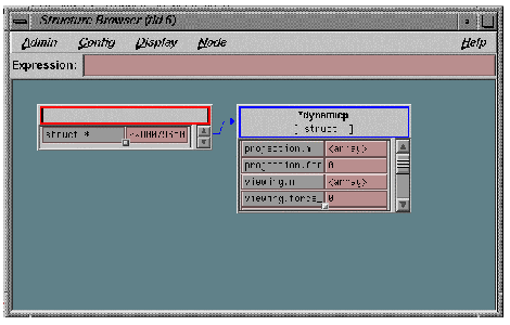
Figure 5-4-11 Display the content of "glistp"
Finally, you can look up the local argument by using, "Variable Browser", if so desired. Select "Views"- "Variable
Browser" from "gvd" main menu with the left mouse button. After the selection, the "Variable Browser" window is displayed and you can look up the content of the local argument.

Figure 5-4-12 Looking up the content of the local argument
7. The Debug Print
On the "N64 Emulator", you can look up the debug print in the program. The display the debug print, "osSyncPrintf( )" set up in the N64 OS function is used. The output result of "osSyncPrintf( )" is displayed in the console which has executed the "gload" command. "simple" is a program which is supposed to display the debug print when the A, B or C buttons of the controller are input; so execute "simple" by using the "gload" command, without using "gvd". When you input the controller button while executing the program, the debug print is displayed in the console window.

Figure 5-4-13 Looking up the debug print
The above is an simple example of the debug. "gvd" has various other functions beside this. Find the best debug method from among these.


